UP-TO-DATE STATIONARY X-RAY UNITS OF CABLE TYPE. SELECTION CRITERIA
category: articlesThe X-ray technique occupies certainly the biggest niche in industrial non-destructive testing. This ensures the continuous appearance of new developments. X-ray unit is a basis for most part of X-ray examination methods. On the market there are a lot of types of X-ray units available that significantly differ from each other by many parameters. Such variety of the types of the units, their parameters and not always correct advertising can nonplus even the experts in the field of radiation methods of testing. In this article I’d like to make an attempt to tell to the readers about main types of X-ray units, their parameters and criteria, according to which the expert can select the necessary X-ray units. I recognize that this is practically impossible to do within one article, but I would try to give maximum useful information.
For the detailed understanding of this article I’d like to get acquainted readers with main axioms of X-raying method.
X-ray testing is carried out by X-raying of the detail under examination with fixation of the image on the X-ray film, reusable phosphorous plates or digital image detector.
Main axioms at the X-raying on the film, on plates or digital detector.
- Higher is the maximum voltage of X-ray unit, thicker steel it could x-ray.
- Lower is the voltage of X-ray tube and higher is its current at the actual exposure, better are the contrast and the quality of the image obtained. It means, to X-ray, for example, steel 20mm thick it would be more correct to set up the parameters of 160kV/5mA/2min., than 190kV/2mA/2min
- Smaller is the focus of X-ray tube, higher resolution could be obtained using geometrical amplification.
- Smaller is the focus of X-ray tube, smaller are its specific power and current, respectively worse would be the contrast of image obtained.
- Closer the film or detector is to the object under examination and longer is the distance from the unit to the object, better is the image quality and less is the influence of the focus size of X-ray tube.
- Higher is the X-ray efficiency of the unit, better quality of the image could be obtained. For example, half-cycle unit is much more effective than the pulsed one. And the unit of constant potential is much more effective than the half-cycle one.
- Higher is the frequency of converting unit, more effective is it.
Main axioms at the X-raying on the film.
- Lower is the sensitivity of X-ray film, higher is the quality of the image.
- Fluorescent intensifying screens deteriorate drastically the image quality.
Main axioms at the X-raying on the digital detector.
- Smaller pulsations of X-ray unit are, higher quality of the image could be obtained.
- Electrical noise, generated by some X-ray units, creates significant distortions in the image, obtained by digital detector.
As you can see some axioms contradict to each other. You would understand what do you need, if continue the reading of this article.
After getting you acquainted with main axioms we pass to the detailed description of the types of X-ray units.
I classify X-ray units first by types of X-ray tube power, then by design and finally by focus size of X-ray tube.
Thus, according to the type of X-ray tube power the units could be divided half-cycle, constant potential of low frequency (500Hz and less), constant potential of medium frequency (1-10kHz) and constant potential of high frequency (more than 10kHz).
Half-cycle X-ray units integrate the step-up transformer, but don’t have a multiplier. The X-ray tube itself which is the diode serves as voltage rectifier. Half-cycle units, as it follows from their name, use only half of high voltage sinusoid, and their efficiency is, at least, two times worse than that of units with constant potential, operating at similar frequency. In addition, the big voltage ratio doesn't practically allow the production of high-frequency X-ray unit. Therefore, half-cycle units operate at low or medium frequencies. In average, the efficiency of half-cycle unit is inferior to the high-frequency unit of constant potential in 4 times.
Low and mid-frequency units of constant potential.
These units already integrate the voltage multiplier and provide the tube with voltage closed to the DC voltage. Unfortunately, the efficiency of the multiplier operation depends on the frequency. The low frequency increases the pulsations of output voltage and decreases the efficiency of the unit. The increase of the capacity of multiplier capacitors could compensate this problem but it would result in sharp increase of the weight and overall dimensions of the unit. Therefore, the low- and medium-frequency units are inferior to the high-frequency ones by efficiency.
High-frequency units of constant potential.
They are the summit of the development. The conversion frequency in such units usually exceeds 20 kHz and in some units achieves 100 kHz. The voltage of the tube could be considered as almost constant. Pulsations are very small. The efficiency of X-ray radiation yield is the highest and is limited only by physics of X-ray tube. The nomographic charts at high-frequency units of constant potential approximately coincide. The difference in the frequency doesn’t practically have any influence on the efficiency and is important only when using with digital detectors.
All X-ray units of series EXTRAVOLT are high-frequency units of constant potential.
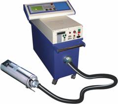 Stationary units of cable type are produced according to one-pole pattern with earthed anode of the tube designed for the voltage 225kV, and according to two-pole pattern with oil cooling of the tubes designed for the voltage of up 450kV.
The one-pole unit consists of high-voltage cathode generator with power block, installed on the top, digital control desk, one-pole X-ray tube, high-voltage cable and anode cooling system of the tube. In one-pole units the anode is cooled with water or antifreeze. Mostly, one-loop system is used, in which water, passing through the anode of the tube comes into the cooler, being cooled with powerful fan. For saving purposes it is possible to cool one-pole tubes with water from water supply system. In this case it is necessary to install the filter with pore diameter of at least 1mcm and digital water flow meter that would automatically switch off the unit if the flow rate of water passing through the tube would become lower than the admissible value.
In two-pole units the high voltage on the X-ray tube is generated by two high-voltage generators of different polarity. For example, two generators by 225kV create the voltage of 450kV on the X-ray tube. Such unit has an additional high-voltage anode generator and additional high-voltage cable. One power block is usually applied for both generators. In two-pole units the anode of X-ray tube is under high voltage (half of the tube voltage) and it could be cooled only with special high-voltage oil. For this purpose special oil cooling systems are used. They are available in two types. First type is oil-air one-loop cooling system. Like the cooling system of one-pole units this system has one liquid loop, passing through the cooler; the unique difference consists in that this loop is filled with high-voltage oil instead of water. The second type of cooling system is based on two-loop principle. The first loop is filled with high-voltage oil which is blown by powerful pump through the anode of X-ray tube and comes into the expansion tank of rather big volume. Inside the expansion tank the pipes of second loop through which cold water from water supply system passes, are arranged so that oil is cooled. At high environmental temperatures it is preferable to select the second type of the systems as the water cooling provides lower temperature of oil and longer service life of X-ray tube accordingly.
High voltage generators integrate the high-voltage transformer generating 25kV and the multiplier that increases this voltage to 160/225 kV. The cathode generator also integrates the incandescent transformer to power the filament of X-ray tube. Transformers and multiplier are immersed into high-voltage oil. All distances between high-voltage parts of generator are designed with 3-4-fold redundancy. Huge safety factor plus the ease of repair and maintenance make the stationary cable units very long-lived. The service life of such unit could exceed 20 years. The substitution of such unit is mostly substantiated by moral obsolescence of machine than by any technical problems.
The big volume of generator allows the use capacitors of higher capacity and diodes, accepting high currents, in multipliers. As a result the power of the units could achieve 6 kW. Higher power is of first priority when scanning onto the X-ray film. In stationary units of cable type the power is usually limited only by X-ray tube selected.
The application of capacitors of higher capacity reduces the pulsations of such units to decimals of percentage; which makes them ideal for the use in X-ray television systems.
The most important characteristic of X-ray unit is the maximum voltage on the tube and maximum thickness of steel that could be X-rayed by a given unit. These parameters are interconnected. Before to select the unit it is necessary to define the type of material and maximum radiation thickness for X-raying, and based on these data define the required maximum voltage and type of the unit. The maximum thickness for X-raying ordinary steel is given in characteristics. If you need to scan non-standard materials, e.g. heat resistant steels, contact us to get additional recommendations for the selection of the unit.
There is also another fine point in the selection of maximum unit voltage. Maybe, many people know that the usual bulb, designed for 220V, would have a longer service life if it would be connected with the network of 210V. . In this sense the X-ray tube does not practically have any difference with the bulb. If according to the name plate the tube is designed for 225kV, its service life would be longer if connect it to the mains of 210kV. Same relates to the tube loading. It is always better to have the voltage margin of about 10 % and tube loading margin of about 15-20%. This statement is equally valid both for cermet and for glass X-ray tubes.
One of the main components of cable unit is the X-ray tube; therefore we shall arrest our attention to the selection of this component. Main type of the tubes available on world market is cermet tube. One of the leading producers of X-ray tubes is the company THALES ELECTRON DEVICES (France). This giant of world industry produces a large range of components for non-destructive testing, including X-ray tubes, REOPs, flat panel detectors and many others. Therefore, further we would use the range and terminology, adopted at this company.
One-pole X-ray tubes are produced for the voltage of 100/160/225kV, two-polar – for the voltage of 320/350/380/420/450kV. The selection of tube voltage depends on necessary thickness of material to be scanned. When scanning on X-ray film without intensifying screens it is approximately possible to apply following rules: Tubes of 100kV for steel of up to 8 mm, 160kV for steel of up to 25 mm, 225kV for steel of up to 40 mm, 350kV for steel of up to 70 mm, 420kV for steel of up to 100 mm.
Next parameters of the tube are its maximum loading and current. Obvious, higher are these parameters, better is. Unfortunately, the tube loading depends a lot on focal spot size. Smaller is the size of focal spot – lower is the tube loading. There is an empiric rule that the loading within the focal spot makes up 1W per each micron of focal spot. It means that the tube with focal spot of 0.4mm (400 mcm) should operate at the loading not exceeding 400W. Naturally, companies-producers indicate high loading values in maximum parameters. However such competition whose values are higher would not bring any benefit. The service life of the tube in the mode of increased loading is much shorter and taking into consideration the cost of cermet tube this becomes of high priority. Of course, it is possible to understand the task of the company-producer. Quicker the tube would fail (anyway it would operate during the guarantee period), quicker the new tube would be bought. However, these are interests of the company producer as to the interests of company-user they are absolutely opposite. Therefore, further we would follow the rule of 1W/1mcm and don’t recommend to the user to exceed this parameter.
Now, after clarifying, how the limiting tube loading depends on the sizes of focal spot, let’s discuss the matter, what focal spot is of high priority for the user.
There is an everyday opinion that smaller is, better is. Such attitude results in that people buy tubes with very small focus that accept currents of 1-2mA only and doesn’t suit to most part of applications.
What size of focal spot could be considered as optimum from the point of view of radiography and radioscopy (X-ray television). For beginning let’s consider the classic pattern of scanning. It is necessary from the point of view of notion “geometrical amplification”.
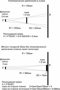 The picture up shows how X-rays, coming out from focal spot, pass through the pore of 1mm and are projected onto the X-ray film (or digital system), creating the pore image two times bigger than the pore itself. This is an example of geometrical amplification in two times. It is clear that closer the object with pore is to the radiation source, bigger the geometrical amplification and the pore image on the film would be. It also could be seen that rays from different focus edges, passing through the edge of the pore, project onto the film not clear image of the pore edge, but a certain projection of tube focus through the pore edge. Let’s call this area as “zone of marginal fogging”. It is absolutely obvious that smaller is size of this zone, sharper and better quality image we would get. On the upper picture it is seen that at the geometrical amplification in two times the fogging zone is equal to the size of tube focus. It means that at the tube focus of 0.4mm and at the amplification in 2 times the fogging zone would also make up 0.4mm. Now, pass to the picture below. Here we have a tube with very big focus of 3mm. But the pattern is given without geometrical amplification. There is a very small amplification due to the thickness of metal being scanned. It means that the pore, located close to the metal side that faces the radiation source, has very small geometrical amplification. On the picture below we could see that in spite of very big tube focus the fogging zone made up 0.088mm only at the most unfavorable position of the pore; which is much smaller than on the upper picture. From here it is easy to conclude that hardly anything depends on the focus itself. Only the ratio between the focal spot size and positional relationship of the object of examination (geometrical amplification) makes sense. From the picture below it could be clearly seen that at the classical X-raying onto the X-ray film when the film is close to the object and the geometrical amplification is close to zero, the focus size doesn’t play any role. Accordingly, it is necessary to choose the tube with maximum loading value and consequently, with bigger size of focal spot of 1.5…3.0mm. In most part of the cases with X-ray television it is impossible to bring the object quite close to the screen of X-ray TV-set. Usually, the distance makes up about 30-80mm. However, even at such distance at the focus size of 3mm the fogging zone would make up about 0.4mm, which corresponds to the upper picture; that is in case of X-ray television the focus of the tube plays more significant role than while X-raying on the X-ray film, but still not decisive role. Based on mentioned above I would recommend to select for X-ray television the focus within the range of 0.2…0.8 mm depending on the geometrical pattern of X-raying. I also recommend to select cermet X-ray tubes with two focuses – one, with small size and small loading; another one with bigger size and bigger loading respectively. For the voltage of up to 160 and 225kV the most optimum are tubes THX-160/0510 and THX-225/0510. They have by two focuses of 0.2 and 0.4mm. The small focus is extremely suitable for the X-ray television and it allows the geometrical amplification up to 6 times. The second focus allows the scanning of objects both on X-ray TV-set with big power to get better contrast and on X-ray film. For the voltage of up to 320/350/380/420/450kV the most optimum are tubes MB-320/3, MB-350/3, MB-380/3, MB-420/3 and MB-450/3. They also have two focuses – 0.8 and 1.8mm.
For those users who actually carry out the examination on the X-ray film, the selection of these tubes would allow further changing over to the digital techniques without necessary changing the tube.
Now, some words about intensification of spatial resolution by using the geometrical amplification. Some articles give different information about that at the amplification, for example, in two times the resolution of X-ray TV-set made 2.8 lp/mm, and at the focus of 1.5 mm it makes 1.6 lp/mm only. The question rises, why, in general, to use the geometrical amplification in order to get the resolution in 2.8 line pairs. At the geometrical amplification in two times the area of image under examination reduces in 4 times respectively. This results in the 4-time increase of the number of pictures and in the increase of examination time. It is not necessary to increase the resolution of bad X-ray television system by reducing the focus of X-ray tube. Good X-ray television systems have the resolution of at least 4-5 line pairs per mm. At the best ones it achieves 10 line pairs per mm. In the majority of cases to have a quality control the resolution in 5 line pairs per mm is more than enough, as the picture resolution begins to be now limited by contrast sensitivity of the installation . In addition, the geometrical resolution in 5 line pairs doesn’t mean at all that we could see only the wire of 0.1mm. On the screen of the system it is easy to see the wire of 40 micron, simply with lower contrast. Therefore the geometrical amplification has sense only for the inspection in certain cases, to increase the contrast sensitivity.
Now, let’s talk about glass tubes and their application. Glass tubes are produced at the plant SVETLANA-ROENTGEN in Saint Petersburg. Unfortunately the selection among these tubes is not big, but it quite satisfies many buyers. The service life of glass tube is inferior to that of cermet ones, however if use glass tubes under lighter modes the difference in service lives practically disappears. Taking into consideration that the glass tube is more than in 10times cheaper in comparison with the cermet one, it becomes ideal choice for those who want really save money. For X-ray television we can recommend rather good Russian tube designed for 160kV with focal spot of 0.8x0.8mm and another tube, designed for 120kV with focal spot of 0.5x0.5mm. The loading of these tubes is not high – 320W, but quite sufficient for cheap X-ray TV sets. Unfortunately, the choice of glass tubes with small sizes of focal spot is completed. Therefore, if you need to have more than 160kV in the X-ray television installation and you don’t have possibility to buy the cermet tube, you should use the glass tube with bigger focus and bring the object under examination maximum closer to the inlet window of X-ray TV-set. While scanning onto the X-ray film the choice of glass tubes expands. We can recommend tubes designed for 200kV with loading value of up to 1500W; tubes designed for 225kV with loading value of up to 1500W and tubes designed for 300kV with loading value of up to 2500W. The problems begin when the voltage exceeding 300 kV is required. Such glass tubes simply don’t exist.
From all mentioned above about X-ray tubes the conclusion could be made that t scan materials on the film at the voltage exceeding 300kV or to the X-ray TV set at the voltage exceeding 160kV it is necessary to use cermet tubes. To scan onto the X-ray film with voltage less then 300kV it is possible to use glass tubes because of their low price. Finally, to scan onto X-ray TV set at the voltage, lower than 160kV it is better to use the cermet tube in expensive high-quality systems and glass tube in all other systems.
Thus, extremely important is that the stationary cable unit would be compatible both with cermet and with glass tubes. This would allow to the buyer to have bigger freedom of maneuver in the future.
June 17, 2004.
B.Y. Kramer
On the pictures:
Геометрическое увеличение – geometrical amplification
Фокусное пятно – focal spot
Пора – pore
Расплывание краёв – edge blooming
Металл толщиной без геометрического увеличения (плёнка лежит вплотную) – metal … thick (film is close to the object)
Пора на стороне источника – pore on the side of the source
Пора на стороне плёнки – pore on the side of the film